Equipment
-
Class II Biolaboratory
The equipment of our research group includes a class II biolaboratory. Furthermore it is possible to use a clean room class 100 in the Institute of Pharmaceutical Technology.
person responsible: Ines Thiele
-
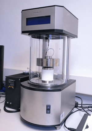
Dynamic material testing
The EPLEXOR® 500 N is used for dynamic material testing, especially for the determination of the absolute value of the modulus of elasticity.
Possible fields of application are:
- DMA/DMTA/DMTS
- Dynamic component inspection
- Lifetime tests
- Analysis of the visco-elastic properties
- Dynamic fatigue testing
- Impact tests
It can mainly be used to investigate thermosets, elastomers and composites. Static loads of up to 1500 N or dynamic loads of up to 500 N are possible.
Equipment specifications:
- Absolute value measurement of deformation, force, sample length L0, temperature
- Determination of the following material parameters E', E", G', G", η", η', tan delta
(depending on the sample holder or tension clamp used) - Simultaneous DMA/DMTS and TMA application
- Control and measurement data evaluation (FFT, Least Square Fit, hysteresis)
- Possible test specimens: polymers, biomaterials, ceramics, metals, films, fibres,
- Composite materials
- Component testing
- Force range: ± 500 N
- Dynamic elongation: 1.5 mm (3 mm)*
- Static elongation: up to 35 mm
- Frequency range: 0.01 Hz - 100 Hz
- Temperature: RT up to 500°C
person responsible:
* maximum elongation depends on the sample, sample holder and frequency
source: Data sheet EPLEXOR® 500 N, GABO QUALIMETER Test GmbH
-
Universal testing machine
The universal testing machine TIRAtest 2710 from TIRA is used to determine mechanical property values from tensile and bending tests. Measurements can be performed on different materials such as metals, ceramics and polymers. Different chucks, test setups and load cells are available. The evaluation is done by means of the software Tiratest-Dynapack.
Equipment:
- mechanical chuck for flat samples (DIN 50125)
- hydraulic chuck for round samples (DIN 50125)
- Setup for 3-point bending tests
- Force transducer HBM S2 (nominal value 200 N)
- Force transducer GTM (nominal value 1000 N)
- Linear encoder MFA 2 mini (nominal value +2 / -1 mm)
- Working area width: 450 mm
- Maximum stroke: 1000 mm
- Maximum testing speed: 750 mm/min
person responsible:
-
FIBSEM
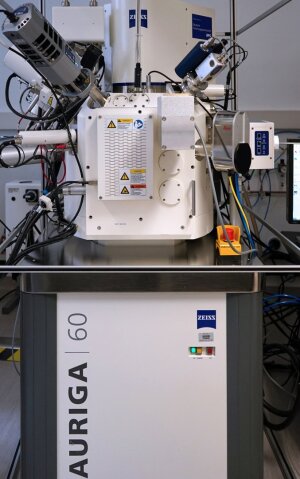
FIBSEM
Image: Fabian Schneider / MatSciAuriga 60® CrossBeam Workstation
Equipment:
- Detectors: Inlense SE, Inlense ESB, SESI, 4QBSD, STEM
- Oxford X-Max EDX detector for 2D and 3D microanalysis
- Oxford Nordlys EBSD detector for 2D and 3D microstructure characterization
- Charge Compensation for non-conductive samples
- FIB (Focused Ion Beam)
- GIS (Gas Injection System with platinum precursor)
- FloodGun (Charge Compensation for FIB)
- Kleindiek micromanipulator
- Atlas system for high-resolution image acquisition and processing up to 32 Kpixel
- 3DSM for 3D analysis of surfaces with 4QBSD detector
person responsible: Ralf Wagner & Dipl.-Ing. (FH) Heidrun Garlipp
-
AFM - Nanowizard
AFM - JPK Nanowizard 4
Image: Fabian Schneider / MatSciThe NanoWizard 4 from JPK BioAFM allows the investigation of surface structure and morphology from the atomic to the macroscopic range, as well as the mechanical and electrical properties of surfaces at speeds of > 70 Hz. For this purpose, the Quantitative Imaging (QI) mode is available in addition to the normal measurement methods such as tapping or contact mode. Furthermore, the instrument is equipped with an electrochemical cell as well as various heating units, which allow investigations in the range of -120 to 300 °C. These can be partially combined with liquid cells or Petri dishes, which allows in-situ investigations. By using an inverted microscope or the BioMat station, optical microscopy and fluorescence microscopy can be combined with the AFM. This allows the superimposition of microscopy images with a positional accuracy of less than one µm for transparent and non-transparent samples.
NanoWizard 4:- Measuring mode: Contact-Mode, Tapping-Mode with Phase Imaging, Qi-Mode, Force spectroscopy, Lateral Force Mode and Force Imaging
- Maximum image size 100 x 100 µm with a maximum Z of 15 µm
- Extension of the measuring range by hybrid stages to 200 x 200 x 200 µm
- Lateral resolution limit is influenced by the peak geometire
- Measurements in liquids in the range from 15°C to about 65 °C
- Motorized sample stage for automatic sample positioning and mapping of larger samples in the mm range
- Cryostage for investigations in the temperature range from -120 °C to about 200 °C
person responsible:
-
AFM - Dimension
The atomic force microscopes Dimension 3100 and Multimode from Veeco (Digital Instruments) with the Nanoscope IV controller allow the investigation of surface structure and morphology from the atomic to the macroscopic range. Various measuring methods are available for this purpose: contact mode and tapping mode, as well as measurement in a liquid cell. In addition, the multimode is equipped with a heating unit, which allows in situ investigations in the range of room temperature up to 250 °C. The Dimension 3100 can additionally determine the hardness of a sample in the micrometer range with the aid of a nanoindenter (Hysitron TriboScope®).
- Measurement mode: Contact mode, Tapping mode with Phase Imaging, Lateral Force Mode and Force Imaging
- Maximum image size 90 x 90 µm (at max. 1024x1024 pixels)
- Lateral resolution limit is influenced by the peak geometry
- Upper vertical resolution limit at 6.14 µm (maximum piezo extension)
- Hysitron TriboScope® Nanoindenter for samples with a Young's modulus > 20 GPa
Hysitron TriboScope®
Special sample features Dimension:
- Sample diameter not greater than 20.3 cm, height up to 1.27 cm
- IMPORTANT: very smooth surface, structures and roughness not higher than the maximum vertical resolution limit (observe sample tilt in the measuring range)
- Special sample feature for nanoindenter: surface must be flat and perpendicular to the indenter
MultiMode
Atomic Force Microscopy Multimode:
- Measurement mode: Contact mode, Tapping mode with Phase Imaging, Fluid Cell, Lateral Force Mode and Force Imaging
- Maximum image size 125x125 µm (at max. 512x512 pixels)
- Lower lateral resolution limit is influenced by the tip geometry
- Upper vertical resolution limit at 5 µm (maximum piezo extension)
- Measurements in the range from room temperature to 250 °C possible
Special features of samples Dimension:
- Dimensions of 2 x 2 cm, height up to 8 mm
- IMPORTANT: very smooth surface, structures and roughness not higher than the maximum vertical resolution limit (observe sample tilt in the measuring range)
person responsible:
-
CLSM
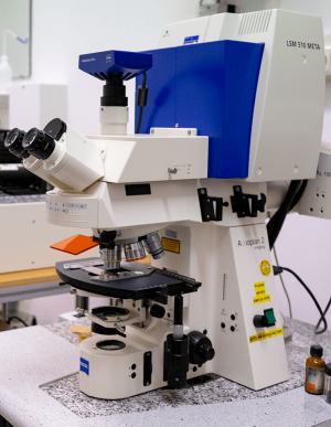
CLSM
Image: Fabian Schneider / MatSciThe LSM 510 Meta is based on the Axioplan 2 research microscope and the 510 Meta confocal module from Zeiss. The software automatically recognises the microscope settings, the objectives used and controls all movements and measurements performed with the system.
Sampling in 8 or 12 bit (256 or 4096 grey levels) is possible. Our "LSM 510 Meta" is equipped with the following three lasers.
- Argon Laser: 458/477/488/514 nm
- Helium-Neon Laser: 543 nm
- Helium-Neon Laser: 633 nm
Objektivausstattung:
- Epiplan Neofluar
- 5x / 0,13mit Zoom 0,7
- 10x / 0,30 HD
- 1800 x 1800 µm & 2606 x 2606 µm
- 921 x 921 µm
- WD > 3,3 mm
- WD = 3,3 mm
- 5x / 0,13mit Zoom 0,7
- Epiplan Neofluar
- 5x / 0,13mit Zoom 0,7
- 20x / 0,50 HD
- 1800 x 1800 µm & 2606 x 2606 µm
- 460 x 460 µm
- WD > 3,3 mm
- WD = 2,0 mm
- 5x / 0,13mit Zoom 0,7
- Epiplan Neofluar
- 5x / 0,13mit Zoom 0,7
- 100x / 0,90 HD
- 1800 x 1800 µm & 2606 x 2606 µm
- 92,1 x 92,1 µm
- WD > 3,3 mm
- WD = 0,15 mm
- 5x / 0,13mit Zoom 0,7
- Epiplan Neofluar
- 5x / 0,13mit Zoom 0,7
- 50x / 0,95 HD
- 1800 x 1800 µm & 2606 x 2606 µm
- 184 x 184 µm
- WD > 3,3 mm
- WD = 0,1 mm
- 5x / 0,13mit Zoom 0,7
- Achroplan
- 5x / 0,13mit Zoom 0,7
- 40x / 0,8 W
- 5x / 0,13mit Zoom 0,7
- Achroplan
- 5x / 0,13mit Zoom 0,7
- 20x / 0,5 W
- 5x / 0,13mit Zoom 0,7
- Achroplan
- 5x / 0,13mit Zoom 0,7
- 63x / 1,4 Oil DIC
- 5x / 0,13mit Zoom 0,7
A halogen lamp and a Hg lamp are available for light microscopy. Light microscopic images can be stored with the high-resolution CCD camera (Axiocam MRm).
Software equipment:
Standard software: Fluorescence: single track, multitrack, Lambda mode with extract channel and linear unmixing function
Topography mode: with profile measurement on straight and curved lines, measurements of lengths, angles, areas and intensities, roughness and volume
Additional equipment:
3D for LSM: 3D display and measurement of volume data sets on external computers
Achievable resolution:
- Size of the excitation region (→ fluorescence mode) determines the resolving power
- z - expansion / vertical or axial resolution depends on the numerical aperture (NA↑, zmin↓) of the objective, the wavelength (λ↓, zmin↓) as well as the pinhole diameter (dpinhole↓ zmin↓) → "optical section thickness" → size of the Airy - disk plays a role (diffraction effects)
- lateral resolution depends on the pixel size (x,y) of the lens used, the number of pixels per shot and the selected digital zoom (all adjustable at the touch of a button)
Fluorescence-Mode:
Three confocal channels with separately adjustable and positionable pinhole. Two highly sensitive Photo Multiplier Tubes (PMT's), each with 8 selectable emission filters, ensure that only the photons of the desired wavelength are detected, as well as a 32-channel meta-detector equipped with a highly efficient optical grating with 10.7 nm resolution for fast acquisition of lambda stacks.
3D examinations (reflection mode):
- no emission filters necessary
- Light is directed onto the sample by semitransparent mirrors
→ 80% transmission, 20% reflection (only this light reaches the sample)
→ 80% of the reflected light is transmitted to the detector, the rest is deflected - Use of the entire spectral range
The smallest z-stack step size is ≤ 25 nm
person responsible: Dipl.-Ing. (FH) Heidrun Garlipp
-
OM
Mikroskop Leica DMR
The Leica DMR XE microscope is a research microscope. Possible observation modes are reflected light or transmitted light. It is equipped with different objectives for brightfield, darkfield or phase interference contrast observation. A 3 megapixel camera (Leica DFC 295) is also available for examination. The QForm or QWin V3 software can be used for evaluation.
person responsible: AOR PD Dr. Jörg Bossert
-
OM2
Mikroskop Leica DM2700M
The Leica DM2700M microscope is a research microscope. Possible observation modes are reflected light or transmitted light. It is equipped with different objectives for brightfield, darkfield or phase interference contrast observation. A 3 megapixel camera (Leica DFC 295) is also available for examination. The QForm or QWin V3 software can be used for evaluation.
person responsible:
-
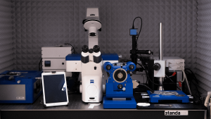
Ellipsometer
Ellipsometer
Image: Fabian Schneider / MatSciThe Accurion Nanoflim EP³-SE ellipsometer provides the following:
- the analysis with highest accuracy and precision
- Investigations on multilayer/multi parameter systems
- the selection of a suitable wavelength for absorbent materials
- optimum sensitivity via wavelength adjustment
main parameters:
- Nulling Ellipsometer in PCSA configuration
- Solid state laser (514 nm, 20 mW)
- separate spectroscopy box with Xenon Arc lamp and 46 interference filters in the range between 360 and 1000 nm
- 768 x 572 pixel CCD camera
- 10x objective
- epView- model Software
- motorized goniometer
- automatic sample changer
- absolute measuring error (thickness): 0.8 nm
- Relative measuring error (thickness): 3
- absolute measuring error (refractive index): 0.01
- Relative measuring error (refractive index): 0.5
person responsible: M.Sc. Xiaoyuan Zhang
-
Tensiometer
Tensiometer DCAT21
Image: Fabian Schneider / MatSciThe dynamic contact angle measuring instrument and tensiometer DCAT21 allows the measurement of:
- Contact Angles
- Surface and interfacial tensions
- Surface energies
- critical micelle formation concentrations
- Densities
- Sedimentation speeds
- Penetration rates
- Penetration forces
- Penetration resistance.
The measurements can be carried out on solids, liquids, powders and single fibres, and at temperatures up to 250 °C.
person responsible: AOR PD Dr. Jörg Bossert
-
Contact angle measuring device
The contact angle measuring instrument DSA10 MK 2 from Krüss enables the determination of the wetting angle of a lying drop and the contour analysis of a hanging drop. The surface and interfacial tensions and spreading coefficients can be calculated from the measured angles.
- Determination of the contact angle of a drop of liquid on a solid surface
- Analysis of a pendant drop
- Determination of the surface energy of a solid sample
- Measurement of the advance and retraction angle by changing the drop volume
- Samples require a flat surface to determine the contact angle
person responsible: AOR PD Dr. Jörg Bossert
-
Microstructure preparation
Common equipment for cutting, grinding, polishing, etching of materials for light and electron microscopic characterization
person responsible: Ines Thiele
-
Cryopreparation
- Kryoport for Leica VCT 100 Shuttle
Leica EM MED020
- Safety workbench Safe 2020
- BAL-TEC Plunge Freezer for the preparation of cryosamples in liquid propane
- Loading Box for mounting the cryo samples
- Leica EM MED020 for sputtering and freeze breaking of cryo samples
person responsible: Ralf Wagner & Dipl.-Ing. (FH) Heidrun Garlipp
-
Powder characterization
Powder manufacturing:
- Hydrolysis or sol-gel process for the preparation of oxide ceramics
Powder preparation:
- Mills for comminution into a wide range of particle sizes
- Jaw crusher
- Vibrating Cup Mill
- Falling ball mill
- Mortar grinder
- Attritor
- Tumble mixer
- Ultrasonic disintegrator
person responsible: AOR PD Dr. Jörg Bossert
-
Zetasizer Nano ZS
The Zetasizer Nano from Malvern Instruments Ltd. can be used to measure the size, electrophoretic mobility of proteins, zeta potential of colloids, nanoparticles and polymer solutions. The system works in the flow configuration also as a size detector.
- Measuring mode: particle size and molecular size
- Measuring range: 0.3 nm - 10.0 µm (diameter)
- Measuring principle: Dynamic light scattering
- minimum sample volume: 12 µl
- Measuring mode: Zeta potential
- Measuring range: 3.8 nm - 100 µm (diameter)
- Measuring principle: Electrophoretic light scattering
- minimum sample volume: 150 µl
- Accuracy: 0.12 µm cm/V s for aqueous systems using NIST SRM1980 standard reference material
- Sensitivity: 10 mg/ml (BSA)
person responsible:
-
UV/Vis-Spectroscopy
- Manufacturer: PerkinElmer®
- Range: 190 nm - 1100 nm
- Bandwidth: 0,5 nm - 4 nm (variable)
- Modes of operation:
- Scanning
- wavelength program
- time-dive
- rate
- quant
- scanning quant
- properties:
- true double-beam operation
- high throughput, low stray-light optics
- pre-aligned deuterium and tungsten-halogen lamps
- Wide range of accessories and consumables
- UV WinLab Software
- Advantages:
- high stability, accuracy and reproducibility
- fast sample changing
- Routine analysis of liquids, solids, pastes, powders, gases
person responsible:
-
XPS
The Quantum 2000 X-ray spectroscope from the company Physical Electronics makes it possible to determine the composition of a wide variety of samples with high resolution using X-ray radiation.
Technical data
Informations:
- Identification of the elements from Li to U
- Quantitative statements on composition according to standards
- Determination of chemical states (bonds, oxidation states)
- Depth profiles of the element distribution:
- up to approx. 1 µm by local, stepwise removal of the sample with an ion beam
- from 2 nm - 30 nm non-destructive through angle-dependent measurement
Lateral resolution:
- approx. 10 µm by "focused" detection
Depth range:
- 5 nm - 30 nm (depending on the element)
- for angle-dependent measurement up to 2 nm
- depth profiles are measured in steps of 2 nm - 20 nm
Detection limit:
- 0.1 to 1 atomic percent, more sensitive to heavy element
Sample Restrictions
- maximum sample size 75 mm x 75 mm
- maximum height of the samples 20 mm
- the samples must be vacuum-tight (dry, frozen, etc.)
- the samples should not have too high vapour pressure (should not outgas)
- the samples should not have been cleaned with acetone
- sensitive samples - like polymers - can be altered by X-rays
- other sample requirements not mentioned here should be discussed individually
Forms of analysis
Survey:
- Detected elements of a glass sample at one point
- The elements are displayed on the basis of the bond energy
- the counts on the Y-axis show the intensity
High Resolution:
- Representation of chemical binding states
- the bonding states with other elements are shown here using carbon as an example
Take-Off-Angles:
- non-destructive depth profile of a plastic sample (polymer)
- the atomic concentration in a layer of the sample is measured by changing the angle of penetration
Mapping/Imaging:
- element-dependent representation of structures on the surface
- on the silicon sample was removed by sputtering the oxygen on the surface and the underlying silicon was made visible. By superimposing the individual scans on top of each other, this can be easily recognized
Depthprofile:
- Distribution of elements in a titanium thin film on a glass substrate
Linescan:
- Element distribution over a linear region on an ion-implanted titanium sample
person responsible: Ralf Wagner
-
Dilatometer
The dilatometer of the Netzsch company is used to determine the expansion coefficient and the transformation points as well as to investigate the sintering behaviour. A temperature range from room temperature to 1450 °C can be investigated.
person responsible: AOR PD Dr. Jörg Bossert
-
Differential Scanning Calorimetry (DSC)
DSC (Differential Scanning Calorimetry) measurements are used to investigate transformation points, glass transition and crystallization. We have the DSC 204 F1 of the Netzsch company at our disposal. A temperature range from -70 °C to 700 °C can be investigated.
person responsible: M.Sc. Karl Scheuer
-
Differential Thermal Analysis (DTA)
Differential thermal analysis and thermogravimetry (DTA/TG) is used to determine melting/transformation points and to measure weight loss as a function of temperature. The instrument STA 409 of the Netzsch company is available, which can be used to investigate a temperature range from room temperature to 1450 °C.
person responsible: AOR PD Dr. Jörg Bossert
-
Hot Stage Microscope
The Leica heating microscope can be used to investigate sintering and wetting behavior up to 1600 °C.
person responsible: AOR PD Dr. Jörg Bossert
-
Thermal conductivity tester
The thermal conductivity tester TCT 416 can be used to measure the thermal conductivity of solids in the range from about 0.5 W/m K to 250 W/m K. The test temperature depends on the thermal conductivity of the material to be tested and is in the range of about 30 °C to 60 °C. The evaluation of the test results is done off-line with an IBM-compatible PC.
Test specimen:
Thermal conductivity > 5 W/m K:
- Cylindrical samples: length: 35 mm, Ø 6 mm
- Rectangular samples: length: 35 mm, edge length 5 mm x 5 mm
Thermal conductivity < 5 W/m K:
- Cylindrical samples: length: 20 mm, Ø 6 mm
- Rectangular samples: length: 20 mm, edge length 5 mm x 5 mm
person responsible: M.Sc. Karl Scheuer
-
Plasma spraying system
person responsible: AOR PD Dr. Jörg Bossert
-
Plasma Treatment
PVA TePla IoN 40 Gas Plasma System
The Ion 40 plasma system from PVA TePla enables plasma treatment of specimens up to dimensions of 229 x 330 x 483 mm in an oxygen, nitrogen or argon atmosphere (other gases possible). The achievable atmospheric pressure ranges from 0.2 - 3.0 mBar (120 - 2000 mTorr). The available power is max. 600 W and is provided by an RF generator operating at 13.56 MHz. Applications range from chemical modification or activation of surfaces, removal of organic contaminants, to a superficial sputtering removal process. The parameters of the system are programmable in such a way that different machining processes can be realized in one cycle.
person responsible: Ralf Wagner
-
Electrospinner
Electrospinning is a versatile key technology for the production of polymeric nanofibers. Nanofibers are used in tissue engineering as carrier material for cells, are an important tool in filtration and are also used as sensors. With conventional processes it is usually not possible to achieve fiber diameters below 10 µm. However, electrospinning allows the continuous production of polymer fibers with diameters of 500 nm with relative ease. In electrospinning, the polarized polymer solution or polymer melt is accelerated onto a target in an electrostatic field with voltages around 30 kV. Local field elevation leads to fiber formation, which is then stretched by the high electric field.
Solvent electrospinner
All polymers that can be dissolved in a suitable solvent at room temperature can be processed. Fiber diameter depends strongly on the process conditions, but can be adjusted to about 500 nm with appropriate parameter selection (which depends on the polymer/solvent combination). Both tile and oriented fabrics can be produced.
Melt electrospinner
All thermoplastics with a melting point below 150 °C can be processed. Fibers diameters are in the range of 5 µm, as the viscosity of the starting material is very low due to the process technology.
is high. Both tile and oriented fabrics can be produced.person responsible: M.Sc. Karl Scheuer
-
3D Printing Device
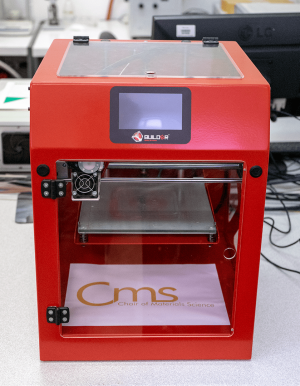
3D printer
Image: Fabian Schneider / MatSciThe Builder Premium Dual-Feed is a 3D printer which works according to the principle of Fused Deposition Modeling. Thereby thermoplastic filaments are melted to print the prototype line by line. The Dual-Feed can print prototypes in two different colors or materials. A gradient structure of the two colours is also possible, allowing any number of gradations of the colour spectrum. With a maximum print space of 205 x 215 x 200 mm the printer is more suitable for smaller prototypes. Due to the complete enclosure of the device a high temperature stability during printing can be achieved.
person responsible:
-
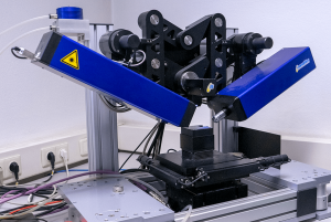
CNC Control Systems for High Speed Machining
Ultrasonic 20 linear Sauer
The high-speed machining centre Ultrasonic 20 linear Sauer is used for machining biomaterials. There is the possibility of 5-axis machining and the combination of "HSC milling" with ultrasonic-supported grinding. Thus, 3D free-form surfaces can be realized even with materials that are difficult to machine. These can be processed flexibly ("individual implants").
person responsible: Prof. Dr. Klaus D. Jandt
-
Compactors
- Cold isostatic press up to 600 MPa
- Uniaxial press up to 450 kN
- Cylindrical press dies in the diameters 10 mm to 30 mm
- Pressing die for bar moulds (5 mm x 45 mm)
- Pressing die for panel moulds (60 mm x 60 mm)
- Hot casting plant
person responsible: AOR PD Dr. Jörg Bossert
-
Micro Contact Printing
- Substrate holder for 2 cm slides, positionable via micrometer screws (X, Y), alignment accuracy: 1 µm
- Stamp holder for 2 cm stamps
- stamping/dry: by hand
- Video System: Dino-Lite Pro HR
- Stepper motor: 50 nm steps
person responsible: Dr.-Ing. Christian Helbing
-
Microwave oven
Microwave in materials technology
Microwave ovens are well known in house hold appliances. Although for most users this technology is still a mystery, it is widely used to heat meals, defrosting of frozen food, and some advanced microwaves even use it for cooking meals.
So many people have experienced advantages from this technology, however many people have also discovered some strange effects such as a small spark during heating, that different food on the same plate has different temperature, some plates become hot some don't …
The effect that microwaves are dissipated in materials with high dielectrical losses leading to an internal heating of the material lead to inspiration for many ideas and visions microwaves could be used for in materials technology. The potential and the principles of microwave heating had been described decades before, for instance in W.H. Sutton: "Microwave Processing of ceramic Materials, Ceramic Bulletin, Vol. 68, No.2, 1989, A.C. Metaxas, R. Meredith, "Industrial Microwave Heating", Peter Peregrinus Ltd. London, UK, ISBN: 0-906048-89-3,1988. Applications and research was reported on many conferences and in journals.
Despite these efforts, microwaves have not become a break through technology in materials science like lasers although investigations started at about the same time. There may be many reasons for this; the difficulty to control the field distribution in the material to be treated, the interaction between the material and the field are certainly the most crucial ones. Recently the increasing demand for composites and the rising energy prices led to an emerging interest in microwave technology.Microwave data
Laboratory microwave-oven I
- Power: 2 kW
- Number of magnetrons: 1
- Frequenzy: 2.45 GHz
- Temperatur: fibres optical sensors (RT-220°C)
- measurement: Pyrometer: 600°C - 1800°C
- Sample holder:
- horizontal Dilatometer (Netzsch)
- Alternative: fused silica table
- Investigation of microwave - material interaction of small samples with local fied concentration
Laboratory microwave-oven II
- Power: 27 kW
- Number of magnetrons: 1
- Frequenzy: 2.45 GHz
- Temperature measurement (In situ): fibres optical sensors (RT-220°C)
- Temperature evaluation (after microwave treatment): thermo camera
- Dimensions of cavity: 140 cm x 170 cm x 60 cm
- Maximum force: 1000 kN
- Number of magnetrons: 30
- Purpose: Microwave treatment of larger parts in a homogeneous microwave field
Microwave curing of composites
IMT and Schmuhl Faserverbundtechnik GmbH & Co.KG have realized a project to use microwaves in a Resin Transfer Moulding (RTM) process for fabrication of fibre composites. The RTM process is characterised in a way that fibers are placed in a two folded tool. When the tool is closed the resin is injected in the mold. In this way the resin is squeezed through the mold, infiltrating the fibres. The closing force of the tool has to withstand the injection pressure which typically leads to a pressure of 4-7 bar in the mold. The advantage of this technology is that costs of the tool are relatively low compared to metallic tools since they can be prepared in a replication of the model itself. If this technology is applied for large parts a low viscosity of the resin and a long shelf life is required before the curing process can start. Therefore epoxy resins are used which have to be heated up to or more than 60 °C for curing. When the mold has to be placed in an oven, even when the heating elements are included in the mold, heating and cooling is a long lasting process, often for several hours. Besides the time consuming process much energy is wasted heating and cooling the form, whereas only the heating of a few millimetres in thickness is required.
To overcome this time and energy restrictions a microwave device for curing large composite parts was build at IMT in cooperation with the company Schmuhl, supported by the Thuringian Ministry of … The principle was to ensure the know how in RTM of company Schmuhl and in integrating the microwave in the production process rather than to adopt the production process to the design of the microwave cavity.The device consists of a cavity with inner dimensions of 140 cm x 170 cm x 60 cm (height). The cavity is equipped with a hydraulic system having a maximum force of 1000 kN and a traverse path of 10 cm. The device is equipped with 30 Magnetrons with a power of 900 W each. 15 magnetrons are located at the upper part and 15 at the bottom. The power of each magnetron can be adjusted separately. Several magnetrons are grouped together. The power of these groups can be controlled during the process. Temperature is controlled during the process by optical fibres at selected points. Temperature distribution is assessed by the help of a thermo camera after the device is opened.
Because of the resin transfer moulding process it is difficult to include mode stirrers in the chamber or to change the shape of the cavity. Therefore the homogenous heating is achieved by the power control of each magnetron and the pulsation of groups of magnetrons.Microwave heating of polymers
In the laboratory microwave system time temperature behaviour of polymers in a microwave field can be investigated. The system is designed to produce high field concentration reproducibly at special places in the chamber.
At this place the sample is placed on to a silica sample holder. In general a sample in the dimensions of 50 mm x 50 mm x 5 mm is prepared and 4 holes are drilled from the outside to the centre. In these holes optical fibre sensors can be placed to measure the temperature. The sensors are located close to the region of maximum power in order not to destroy the sensors in case of a thermal run away. Temperature distribution can be determined after the experiment by a thermal camera.The microwave power is kept constant and the temperature increase is recorded. In this way different materials can be compared how microwave power leads to temperature increase.
Microwave Sintering
Microwaves and convential furnaces are regularly used as a drying process in the ceramic industry. Much work has been reported regarding the sintering of ceramics and the two techniques have often been compared. Commonly it has been stated that microwaves lead to lower sinter temperatures compared to conventional processes. However, such comparisons are difficult to accurately ascertain as heating rates under microwave conditions quite often are much faster than in conventional furnaces. The methods used for assessing these properties is usually with the aid of a thermocouple, but this makes direct comparison between the two methods unreliable as the temperature measurements are usually made at or close to the surface of the sample.
To over come the draw backs of using a thermocouple we have developed a special furnace at the IMT, this will be used to simulate conventional sintering (sample is heated by an external heat source and heat is transferred from the surrounding area to the sample) with microwave sintering (where the heat is generated in the sample itself and heat transfer takes place from the sample to the surrounding). The furnace is equipped with a microwave source and an inductive heating system. With microwave energy the sample is radiated directly or preheated by silicon carbide. To reduce heat loss at the surface the sample is placed in an insulation of alumina refractory material. In case of HF heating the sample is placed in a carbon susceptor and the carbon cylinder is heated by induction. Temperature is monitored in both cases by a pyrometer. The temperature can be measured on the surface of the sample or inside a hole drilled into the sample.
To investigate the shrinkage behaviour a dilatometer is included in the system. The sample holder is specially designed to be suitable for microwave conditions.Titania dissipates microwave energy at higher temperatures effectively. This means that it has to be preheated by silicon carbide. At about 900°C the titania ceramic is heated directly by dielectric losses. This can easily be seen when comparing the temperature rise versus time of a titania sample to a alumina sample of same size and shape. Since alumina shows very low dielectric losses it is only heated by the silicon carbide elements nearby which are heated by the microwaves.
person responsible: AOR PD Dr. Jörg Bossert
-
Tempering
- Sintered dilatometer up to 1600 ºC
- Medium temperature furnaces up to 1200 ºC
- Medium temperature furnaces up to 1340 ºC (temperature program controlled)
- High temperature furnaces up to 1800 ºC (temperature program controlled)
- Glass melting furnace up to 1600 ºC (temperature program controlled)
person responsible: AOR PD Dr. Jörg Bossert
-
QCM-D Q-Sence
Using QCM-D (Quartz Crystal Microbalance with Dissipation monitoring) it is possible to determine mass changes with a sensitivity in the nanogram range. Q-Sense is also able to measure dissipation and thus provides information about the structure and viscoelasticity of films.
With the help of the Q-Sense system, for example, the following problems can be investigated:
- Degradation
- Adsorption
- Swelling, water content
- Thickness
- Mass change
- Structural changes
- Interactions
- Networking
Technical specifications:
- Number of sensors: 1
- Volume above each sensor: ~ 40 μl
- minimum sample volume: ~300 μl
- Operating temperature: 15 °C to 65 °C, control via software, stability ± 0.02 K
- Flow rate: 0 ml/min - 1 ml/min
- Sensor crystal: 5 MHz, 14 mm diameter, polished, AT cut, gold electrodes
- Frequency range: 1 MHz - 70 MHz (up to the 13th harmonic, 65 MHz for a 5 MHz crystal)
- maximum time resolution: 1 frequency, up to 200 data points per second
- maximum mass sensitivity in liquid: 0,5 ng/cm2
- normal mass sensitivity in liquid: 1.8 ng/cm2
- maximum dissipation sensitivity in liquid: 0.04 x 10⁻⁶
- normal dissipation sensitivity in liquid: 0.1 x 10⁻⁶
- typical noise peak to peak (QMW) in liquid: 0.16 Hz (0.04 Hz)
person responsible: Dr.-Ing. Christian Helbing